Latest updates:

Simple MIDI controller with four knobs
Back07/03/2026
My project is heavily based on these sources:
- DIY MIDI Controller, by The Nerd Musician;
- theMIDInator, by Switch and Lever;
- Arduino MIDI Controller: Part 1 - Potentiometers, by Notes and Volts.
I'm currently writing this text?article? to document my thought process and to demistify the routine's details. All of the credit goes to these people I've mentioned above.
This was the first project I used some sort of hard-coded communication protocol between circuits. I wanted to make some sort of general purpose controller to make the process of sound design in Ableton a bit more tactile and expressive.
The MIDI controller is composed of a microcontroller (an Arduino Uno/Nano, in this case) and four potentiometers - where, by changing their position/angle, the digital knob value (inside Ableton - or any other DAW, I think) changes accordingly.
As an initial step, I tried creating a simple routine to read the values of all knobs with constant sampling frequency:
This code snippet should be able to show, in the Arduino IDE's Serial Monitor/Plotter (or any other serial monitor/plotting software), the current value of each knob. The necessary electronic connections are shown in the figure below.
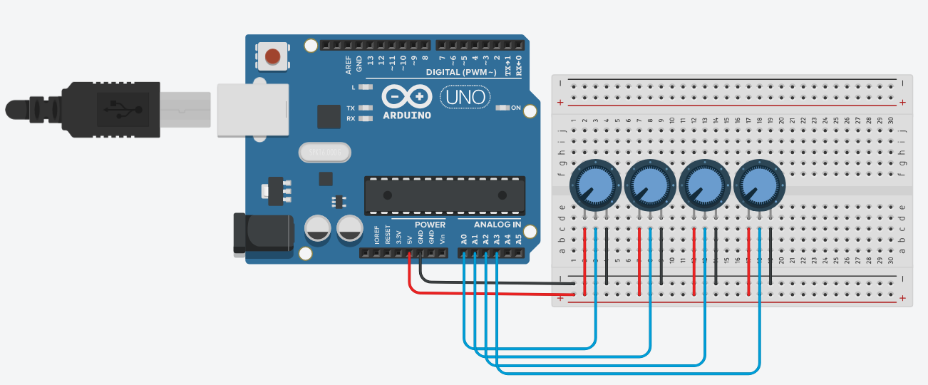
Note: The potentiometer values aren't extremely important in this project - however, by using higher (maximum resistance) values, the read value can be noisier than usual; by using lower values, more current goes through each potentiometer (and more power is dissipated as heat in the potentiometer). In my own physical build, I've used four 10kOhm potentiometers.
The reason as to why I've used the struct vector to define the set of knobs is scalability - I've found it easier to control the number of knobs I wanted to use in this project by altering the struct vector's length. Because this application doesn't need tons of memory and the highest operational frequencies, I didn't try to minimize the routine's memory consumption or number of operations and, instead, tried to make it easier (for me) to understand and tinker with it.
Now, we have to take care of the noise present in this circuit - if you build this on a breadboard (or solder it to a perf. board) you will notice how the values 'jump' around a certain level, specially when considering the combination of the thermal noise with the effect of the quantization process. We can use a first order low-pass digital filter - the exponential moving average - to smooth the output signal:
Note: This step isn't completely necessary - in the next steps the read value will be mapped to a smaller one and consequently the effects of noise might be mitigated along this process. However, I still wanted to introduce this step because my readings kept varying a lot because of noise and faulty breadbord connections (and maybe to flex my knowledge on the most basic digital filter? maybe..).
By choosing a value of alpha (between 0 and 1), we can change the signal's 'smoothness'. Please note that, by using values closer to 0 (e.g. <0 to 0.5), the output signals might change too slowly, making the system feel unresponsive/slow.
We can now use these read values to send MIDI messages to the DAW. By following the codes presented in Table II of the MIDI specification, our simple MIDI message will be comprised of three 8 bit 'packets':
Note: The controller ID nos. are listed in Table III of the MIDI specification.
To send a MIDI message through the serial port, I created the following function:
where data1 is the channel number and data2 is the most recent read/processed value. We are able to send each MIDI message (one for each knob at every new reading) by adapting our previous codes to the following:
Note: From this snippet on, we aren't able to use the Serial monitor/plotter to debug the system's output.
However, while using this routine we are sending a MIDI message with (theoretically, hopefully) frequency equal to the sampling frequency. That means that we're refreshing the digital knob's value whithout considering if there was any noticeable change in said value. So, to make a 'cleaner' routine, we can set a threshold value for the knobs' changes, where we'll only send a MIDI message if the difference between the new read/processed value and the last value is greater than the threshold.
Note: The threshold value (MIN_DIFF) is only used when comparing two 10 bit numbers (the standard Arduino Uno/Nano ADC resolution). Be mindful of your microcontroller's ADC resolution when determining the threshold value.
Finally, the (maybe) complete version of the microcontroller code is presented below.
It is necessary to acknowledge that no potentiometer can reach a value of 0 Ohms, nor every potentiometer is able to reach it's maximum resistance value. Consequently, we aren't always able to span the whole available range for the digital knobs. To fix this, we can change the mapping values as such:
where lowerValue and higherValue can be set to a new pot range (e.g. 100 to 900 or 50 to 1000 instead of 0 to 1023).
By this point our circuit is sending MIDI messages whenever we change a potentiometer's value. However, we still need additional software to make the connection between the serial port and the DAW, specifically hairless-midiserial and loopMIDI. You should be able to debug the microcontroller's output as MIDI messages in hairless-midiserial when you use Serial.write() instead of Serial.print()/Serial.println().
After you've configured these two programs, the whole system should be working! Please send me suggestions on how to improve this project/new ideas for me to work on!